Mechanical engineering
News Update
Loading...

Thursday, May 12, 2022

The Machining Process and the Different Types of Machining Operations !

 Introduction:


There are many different types of machining operations, each of which can produce a different part geometry and surface texture.Turning and milling are the two most common machining techniques. Other processes may be included into or done independently of these processes. A drill bit, for example, can be mounted on a turning lathe or tossed into a drill press. Previously, there was a distinction between turning, in which the part turns, and milling, in which the tool revolves. With the introduction of machining centres and turning centres that can conduct all of the functions of many machines in a single machine, this distinction has become somewhat blurred.

1.   Turning: 


1.     Turning

A single point turning tool rotates axially down the side of the workpiece, removing material to generate various characteristics such as steps, tapers, chamfers, and contours. Typically, these features are machined with a shallow radial depth of cut and many passes until the end diameter is reached.

2.     Facing

turnin operations


A single-point turning tool rotates radially around the workpiece's end, removing a small layer of material to create a smooth flat surface. The face's depth, which is normally very small, can be machined in a single pass or by making successive passes at a reduced axial depth of cut.

3.     Grooving

 A single-point turning tool cuts a groove the same width as the cutting tool by moving radially into the side of the workpiece. Multiple cuts can be performed to build grooves that are larger than the tool width, and specific form tools can be used to generate grooves with different geometries.

4.     Cut-off 

A single-point cut-off tool advances radially into the side of the workpiece, similar to grooving, and continues until the workpiece's centre or inner diameter is reached, thus parting or cutting off a segment of the workpiece.

5.     Thread cutting

A single-point threading tool glides axially down the side of the workpiece, cutting threads into the outside surface, usually with a 60 degree pointed nose. Threads can be cut to a specific length and pitch, and thread formation may need numerous passes.

6.     Drilling

7.     Boring

turning operations
A single-point threading tool slides axially down the side of the workpiece, cutting threads into the outside surface. It commonly has a 60 degree pointed tip. Threads can be cut to a specific length and pitch, and the formation of the threads may need numerous passes.

8.     Reaming

A reamer enlarges an existing hole to the diameter of the tool by entering the workpiece axially through the end. Reaming removes only a small amount of material and is frequently used after drilling to get a more precise diameter and a better internal finish.

9.     Tapping

A tap cuts internal threads into an existing hole by entering the workpiece axially through the end. The appropriate tap drill size that will accept the desired tap is normally drilled into the existing hole.


2.   Milling:

 is the process of removing material from a workpiece by advancing a cutter into it with rotary cutters. This can be accomplished by changing the direction[2] of one or more axes, as well as the cutter head speed and pressure. [3] Milling encompasses a wide range of procedures and machinery, ranging from small single pieces to huge, heavy-duty gang milling operations. It's one of the most used methods for producing custom parts with tight tolerances. A variety of machine tools can be used to mill. The milling machine was the first type of machine tool for milling (often called a mill). Milling machines evolved into machining centres after the introduction of computer numerical control (CNC) in the 1960s: milling machines with automatic tool changers, tool changers, and tool changers. Enclosures, tool magazines or carousels, CNC capabilities, cooling systems Vertical machining centres (VMCs) and horizontal machining centres (HMCs) are the two types of milling centres (HMCs).

milling machine


3.   Drilling:

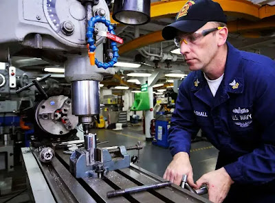
Drilling uses drill bits to generate cylindrical holes in solid materials; it is one of the most significant machining techniques since the holes created are typically used to aid with assembly. Drill presses are frequently employed, however lathes can also be used. Drilling is a preparatory step in most manufacturing operations for producing finished holes, which are then tapped, reamed, bored, etc. to generate threaded holes or bring hole dimensions within acceptable tolerances. Due to the bit's flexibility and tendency to seek the route of least resistance, drill bits will typically cut holes larger than their nominal size and holes that are not always straight or round. 

As a result, drilling is frequently specified undersize. After that, another machining operation is performed to get the hole to its final size. 


drilling machine
drilling machine


Types of drilling machines

Drilling machines come in a variety of shapes and sizes, depending on the type of operation, amount of feed, cut depth, spindle speeds, spindle movement method, and needed accuracy.

The following are the various types of drilling machines:

1. Hand drilling machine or portable drilling machine

2. Bench drilling machine (or sensitive drilling machine)

3. Upright drilling machine

4. Radial drilling machine

5. Gang drilling machine

6. Multiple spindle drilling machine

7. Deep hole drilling machine 


Saturday, March 3, 2012

Tensile Testing

Tensile test overview

Tensile Testing


What does tensile testing entai?

Tensile tests are used to see how materials react under tension. A materials sample is typically tugged to its breaking point in a simple tensile test to determine the material's ultimate tensile strength. Throughout the test, the amount of force (F) applied to the sample and its materials elongation (L) are measured. Stress (force per unit area) and strain (percent change in length) are two concepts used to describe material qualities. The force readings are divided by the sample's cross sectional area to obtain stress (= F/A). Strain measurements are calculated by dividing the change in length by the sample's original length (ε = ∆ L/L). The stress-strain curve is an XY figure that displays these numbers. Measurement and testing The processes differ depending on the substance being evaluated and its intended use.

Tension / tensile tests are performed  test accurately and reliably by ADMET material testing devices. Metals, polymers, textiles, adhesives, medical devices, and a variety of other items and components can all benefit from our technologies. ADMET testing devices precisely determine mechanical parameters such as tensile strength, peak load, elongation, tensile modulus, and yield as they pull materials apart.

Tensile Testing Fundamentals

The key concepts of tensile testing will be discussed in the next section. An ADMET MTESTQuattro-equipped tensile tester provided all software output screens.

Tensile test Strain and Stress 

Tensile test these are the fundamental aspects of material science. The amount of force per unit cross sectional area is known as stress. The ratio of the change in length to the initial length, stated as a percentage, is known as strain. The results of tensile tests are displayed as plots of stress versus strain.

Tensile test Deformation of Elasticity

In tensile testing The region on the stress-strain curve where deformation can be reversed by releasing stress is known as elastic deformation. It's also where tension and strain are mostly proportionate. The initial linear segment of a stress-strain curve can be identified as such. test

 Tensile testing Modulus of Young

Tensile testing the elastic modulus, commonly known as Young's modulus, is a quantity that relates the proportion of stress to strain during elastic deformation. It is the initial slope of the linear section of the graph on a stress-strain curve. The equation =E• represents this relationship. Hooke's Law, which was designed to represent the behaviour of springs, is the name of this relationship.

Tensile testing  Proportional by Proportion

In Tensile testing The first time the plot deviates from the line indicating Young's modulus on the stress-strain curve. This divergence is usually gradual and material-dependent.Performing a Tensile Test

In general, the following equipment is required to do tension testing:

Frame for universal testing machines

Controller and/or indicator for load cells

To hold your sample, you'll need the right grips and fixturing.

The universal test machine frame gives the sample the structure and rigidity it needs to be pulled apart at the proper rate. With a wide range of capabilities, frames are offered in electromechanical 

and servo-hydraulic variants. It's critical to choose a frame that can bear the force required to examine the sample.

Load cells are used to determine how much force is being delivered to the sample. These, like frames, come in a range of sizes. If you use a load cell with a capacity lower than the specified breaking strength, the load cell will break before the sample. In contrast, a load cell with too high a capacity would produce test results that are less precise than required, as load cell resolution often falls below 1%. A 1,000-pound load cell, for example, would have far too much capacity for a sample that breaks under 1 pound of force.

A controller or an indicator may be required depending on your system configuration. The test frame's behaviour during testing, including test speed and displacement, is controlled by controllers, as the name implies. In certain cases, all that is required is an indicator. The test data is captured and displayed through indicators, but they do not control the equipment.

Tension testing can be done with a variety of grips and fasteners. To hold different materials properly, different fixturing is required. Because of how the materials respond when tensile stresses are applied, a sample made of metal, for example, requires different grips than a stretchy piece of rubber. In order to achieve accurate results, you must choose the right grips for your application.

Why Should You Do a Tensile Test?

Tensile testing can be used to determine many qualities of a material. Tensile testing determines the strength and ductility of metals when subjected to uniaxial tensile stresses. The ability of a metal to sustain tensile loads without failing is defined by its tensile strength. Because brittle metals are more likely to break, this is a significant consideration in the metal forming process. A tensile test is often used to choose a material for a specific purpose, to ensure quality, and to predict how a material will behave to various forces. WMT&R offers a variety of tensile testing services, all of which are conducted to established or bespoke specifications. Tensile tests can be carried out at room temperature, at extreme temperatures (-452 to 2200°F), and with a variety of specimen types, fittings, and test protocols.

Tension Testing Problems

Tension Testing Problems One of the most common reasons of erroneous tensile readings is non-axial loading. When utilising a load sensor or force gauge, even minor off-center loading might result in measurement inaccuracies of up to 0.5 percent. It's crucial to make sure the load cell, top test fixture, sample, and bottom test fixture are all perpendicular to one another.

Accurate and consistent results require the use of a correctly sized force gauge or load cell sensor depending on the projected load measurement. A good rule of thumb is to use a sensor that measures between 20% and 80% of the projected load. This will eliminate or reduce errors caused by mechanical noise at the low end. It will aid in the prevention of overloading at the top end of the measurement range. Because most sensors are calibrated and have accuracy specifications based on full scale, the closer you get to zero, the more the accepted error influences your measurement.

Another major source of faulty tensile measurements is using the wrong test fixture. A fixture that is either too large for the sample or applies too much gripping force to the sample during tensile movement can cause the sample to fracture outside of the prescribed gauge length area. The test fixture should be sized according to the expected load characteristics of the sample. Wedge-action test fixtures function well on ductile samples but are less dependable on brittle materials because they apply load to the brittle material.

as axial loading increases, the sample When pneumatically operated test fixtures that adjust the gripping force onto the sample are used, brittle materials tend to test more consistently.

Inconsistent and erroneous characterisation might result from poor sample preparation. The sample should be prepared to the necessary dimensions when testing to a specific international standard. The component will typically be used in its completed state for force measurement applications. Material testing, on the other hand, employs specifically prepared specimens in a variety of shapes and sizes. Their cross-sections can be circular, rectangular, or square, and their gauge length is known.

Another common reason why tensile measurement may not be optimal is testing at too fast or too slow a velocity. Testing should be done in line with a known and accepted standard whenever possible.

ASTM, ISO, DIN, or other recognised testing standards The test speed is fully described in these standards, ensuring accurate measurement.Temperature can have a big impact on tensile outcomes. The elasticity of a sample can be dramatically reduced as the temperature rises.

Featured

[Featured][recentbylabel]

Featured

[Featured][recentbylabel]
Notification
This is just an example, you can fill it later with your own note.
Done