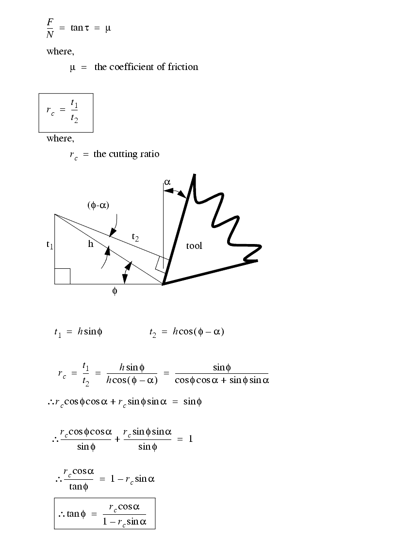
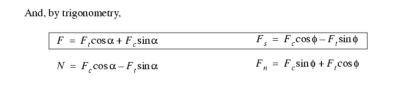
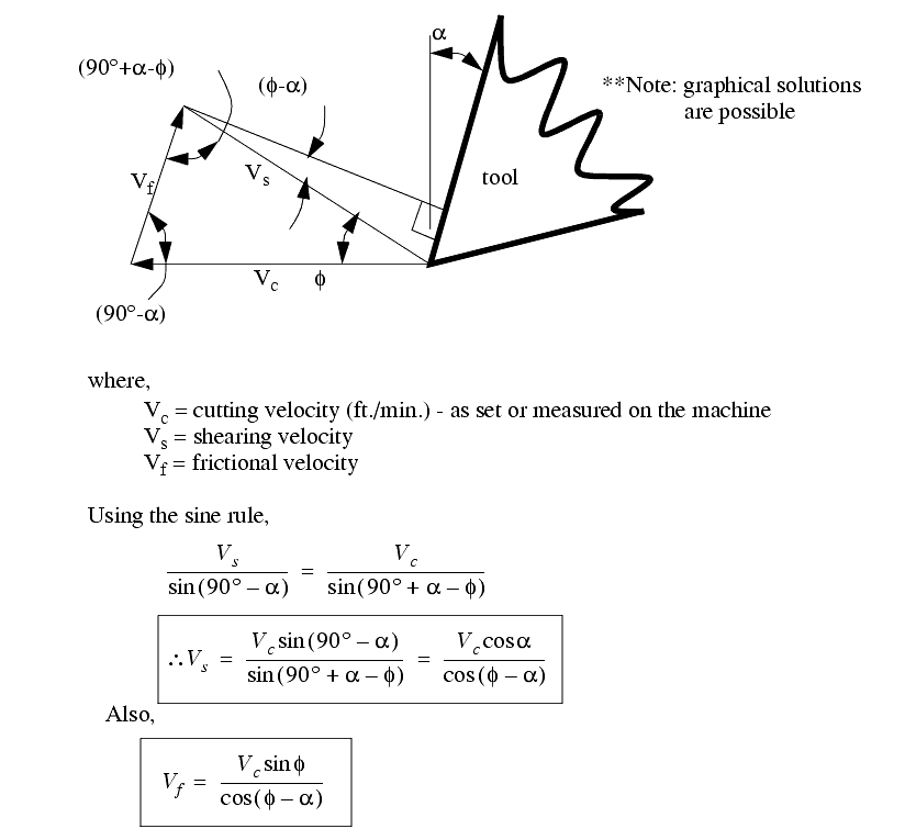
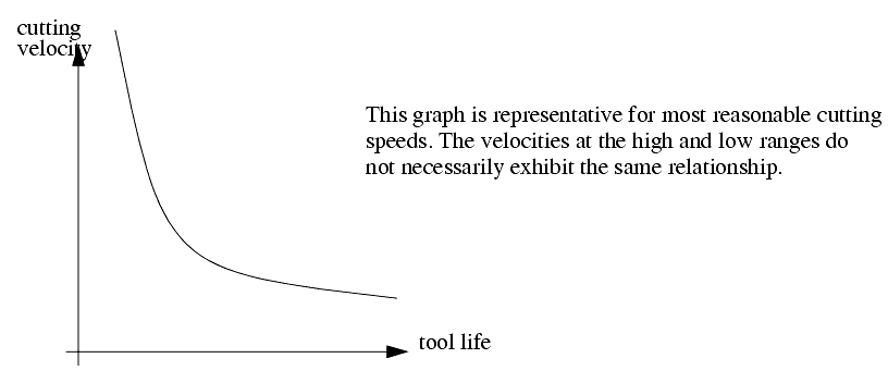
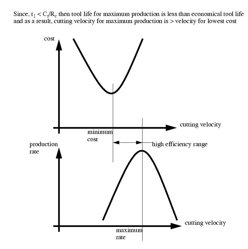
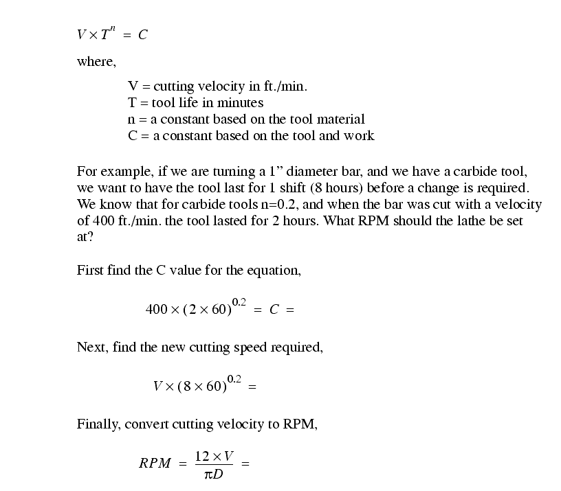
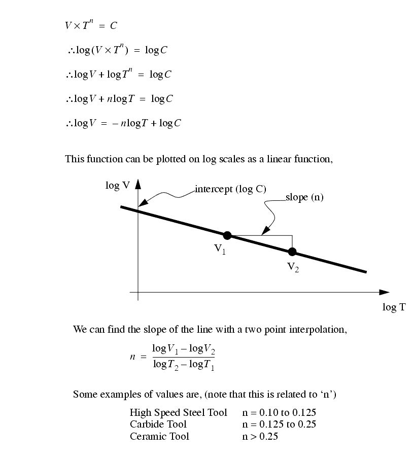
Mechanical engineering
News Update
Loading...

Thursday, February 17, 2011

Welding

Welding

Welding  is a fabrication or sculptural process that joins materials, usually metals or thermoplastics, by causing coalescence. This is often done by melting the workpieces and adding a filler material to form a pool of molten material (the weld pool) that cools to become a strong joint, with pressure sometimes used in conjunction with heat, or by itself, to produce the weld. This is in contrast with soldering and brazing, which involve melting a lower-melting-point material between the workpieces to form a bond between them, without melting the workpieces.

Many different energy sources can be used for welding, including a gas flame, an electric arc, a laser, an electron beam, friction, and ultrasound. While often an industrial process, welding can be done in many different environments, including open air, under water and in outer space. Regardless of location, welding remains dangerous, and precautions are taken to avoid burns, electric shock, eye damage, poisonous fumes, and overexposure to ultraviolet light.

Until the end of the 19th century, the only welding process was forge welding, which blacksmiths had used for centuries to join iron and steel by heating and hammering them. Arc welding and oxyfuel welding were among the first processes to develop late in the century, and resistance welding followed soon after. Welding technology advanced quickly during the early 20th century as World War I and World War II drove the demand for reliable and inexpensive joining methods. Following the wars, several modern welding techniques were developed, including manual methods like shielded metal arc welding, now one of the most popular welding methods, as well as semi-automatic and automatic processes such as gas metal arc welding, submerged arc welding, flux-cored arc welding and electroslag welding. Developments continued with the invention of laser beam welding and electron beam welding in the latter half of the century. Today, the science continues to advance. Robot welding is becoming more commonplace in industrial settings, and researchers continue to develop new welding methods and gain greater understanding of weld quality and properties

Wednesday, February 16, 2011

What is the role of a Production Engineer?

What is the role of a Production Engineer?


Production engineering

 is a combination of manufacturing technology with management science. He should typically has a wide knowledge of engineering practices and is aware of the challenges related to production. The goal is to accomplish the production in the smoothest, most-judicious and most-economical way.

Also encompasses castings, joining processes, metal cutting & tool design, metrology, machine tools, machining systems, automation, jigs and fixtures, and die and mould design. Products engineering overlaps substantially with manufacturing engineering and industrial engineering.

In industry, once the design is realized, production engineering concepts regarding work-study, ergonomics, operation research, manufacturing management, materials, production planning, etc., play important roles in efficient production processes. These deal with integrated design and efficient planning of the entire manufacturing system, which is becoming increasingly complex with the emergence of sophisticated production methods and control systems.

Production Engineer

Work opportunities are available in public and  may be in private sector manufacturing organizations engaged in implementation, development of new production processes, information and control systems, and computer skills controlled inspection, assembly and handling.

What is the role of a Production Engineer?

A Production Engineer devises and implements techniques for improving manufacturing operations. Examines current processes and devises methods to boost productivity or cut expenses. A Production Engineer ensures that established production procedures and quality standards are followed. A bachelor's degree in engineering is required. Production Engineers usually report to a manager or the head of a unit or department. A Production Engineer normally has 10+ years of expertise in the field. Works on advanced, complex technical projects or commercial issues that require cutting-edge technical or industry expertise. Works independently. Goals are usually expressed in terms of "solutions" or "project goals." Because of his or her specialisation, he or she may be able to lead the work group.

Jobs and career in Production Engineering, Salary, and Top Recruiters

Production engineers have a huge job market in worldwide. Individuals with a degree in engineering are employed in a variety of industries, including pharmaceuticals, research labs, manufacturing, communication, travel, sports, health, and information technology, among others.

Following are some of the occupations available to production engineers after completing a course in the field:

  1. Production Engineer
  2. Engineering Plant Production Manager
  3. Process Engineer
  4. product engineer
  5. Industrial Managers
  6. Quality Engineers
  7. process engineer
  8. Management Engineer
  9. Operations Analyst
  10. Manufacturing and design Engineer
  11. Architectural and Engineering Managers
  12. Cost Estimators
  13. Health and Safety Engineers
  14. Industrial Engineering Technicians
  15. Industrial Production Managers
  16. maintenance engineer
  17. Logisticians
  18. Management Analysts

Salary for Production Engineers

A production engineer's remuneration varies depending on their level of experience. It is entirely determined by the years of experience and skill set required for the position. See the estimated average yearly salary for the various levels is E£ 61,042.

Production Engineer Responsibilities:

  1. Supervising manufacturing processes and ensuring that will work is completed in a safe and efficient manner are among the responsibilities of him.
  2. Collaboration with other engineers on initiatives to enhance production, costs, and labour requirements.
  3. Identifying production line issues and giving advice and training.
  4. Creating safety processes and standards that consider the workers' well-being while simultaneously reducing the carbon footprint.
  5. Keeping up with engineering and production advances and exchanging knowledge with coworkers.
  6. Unsafe practises must be identified, documented, and reported.
  7. Creating project production schedules and budgets.
  8. Meetings with appropriate departments and stakeholders are being planned.
  9. Analyzing and recommending improvements to all aspects of productiona.
  10. Obtaining any necessary materials and equipment.

Modern technology tools and software desien products 

  • SolidWorks

 is  an mechanical engineering software  and a computer programme for CAD modelling that was created by Dassault Systèmes.
SolidWorks is an industrial standard for generating physical object designs and make design specifications, with over 165,000 organisations using it as of 2013.

  • AutoCAD

Autodesk's AutoCAD is an example of a CAD modelling computer programme. CAD modelling and CAE are also common uses for AutoCad. 

Product life cycle management (PLM) tools and analysis tools used to run complicated simulations are two other CAE applications often utilised by product manufacturers. Product response to expected loads, including fatigue life and manufacturability, can be predicted using analysis techniques. Finite element analysis (FEA), computational fluid dynamics (CFD), and computer-aided manufacturing are examples of these techniques (CAM). A mechanical design team can iterate the design process fast and cheaply using CAE systems to build a product that better satisfies cost, performance, and other limitations. There's no need to build a real prototype until the design is nearly finished, allowing hundreds or thousands of people to test it.
CAE analysis programmes can also model difficult physical phenomena that are impossible to address by hand, such as viscoelasticity, complex contact between mating components, and non-Newtonian flows.

Multidisciplinary design optimization (MDO) is being utilised with other CAE tools to automate and optimise the iterative design process, just as manufacturing engineering is integrated with other disciplines like mechatronics.
 MDO solutions automate the trial-and-error procedure employed by traditional engineers by wrapping around existing CAE processes. MDO employs a computer-based technique that seeks for superior alternatives iteratively from an initial guess within defined parameters. This process is used by MDO to determine the optimum design outcome and to list numerous possibilities. 

What qualifications are required of a Production Engineer?

When considering a position like this, you must consider your talents and abilities. The capacity to excel in this profession is contingent on the following abilities: Process Engineering, Process Mapping, Process Optimization, and Production Engineering are all examples of mathematical modelling. Although not always required, knowing how to use CAD software, CAE software, and a quality management system might be beneficial (QMS). Attempt to convey your mastery of these talents during an interview.

Industrial engineers design efficient systems that integrate employees, equipment, materials, information, and energy in order to produce a product or provide a service.

Working Conditions

Industrial engineers work in offices or in the environments they are aiming to change, depending on their job. When observing difficulties, they may, for example, see industrial workers assembling parts. They may be in an office at a computer, looking at data that they or others have acquired when solving problems.

What Does It Take to Become an Industrial Engineer?

A bachelor's degree in industrial engineering or a similar discipline, such as mechanical or electrical engineering, or industrial engineering technologies, is often required of industrial engineers.

Pay

In May 2021, the median yearly wage for industrial engineers was $95,300.

Job Prospects

Industrial engineers' employment is expected to expand 14% between 2020 and 2030, faster than the average for all occupations.

On average, throughout the next decade, there will be about 23,300 jobs for industrial engineers. Many of those positions are projected to arise as a result of the need to replace people who change occupations or leave the workforce for other reasons, such as retirement.

Data by State and Region

Find job and wage information for industrial engineers by state and region.

Occupational Groups

Industrial engineers have similar job duties, education, job growth, and salary to other occupations.

Making Your Mark

Manufacturing engineering majors are beneficial in both engineering and business operations. Almost all manufacturing engineering graduates have begun their professions or completed their education within six months of graduation in recent years. Boeing, John Deere, Borgwarner, HNI, Caterpillar, Deublin, and Kohler are among the companies where they work.


Friday, January 7, 2011

The changing face of part inspection

The changing face of part inspection

 October 21, 2010

* Authored by: Ron Branch, Verisurf Application Engineer, Verisurf Software Inc., Anaheim, Calif. Resources: Verisurf Software Inc., verisurf.com
* Inspection software helps 3D CAD, 3D GD&T, and measuring devices work together to ensure design intent.

A necessary component of the model-based definition (MBD) approach to product design is 3D geometric dimensioning and tolerancing (GD&T), a universal symbolic and tolerancing language. In the MBD approach, the 3D CAD model is the authority, providing all the detailed product information for the entire product life cycle. The method moves the 3D CAD model from design to a manufacturing orientation, and lets software automate and validate steps in simulation, manufacturing, and inspection, thereby reducing human error.

Verisurf X illustrates high and low tolerance deviations on associated model-based GD&T specs.

Last updated in 2009, GD&T has been rigorously studied and applied by thousands of manufacturers around the world. It is often considered essential for communicating design intent — that is, that parts from technical drawings have the needed form, fit, function, and interchangeability. The recent update includes changes in feature design, datum references and degrees of freedom, surface boundaries and axis methods of interpretation, profile tolerances, and symbology and modifiers tools.

In manufacturing, the direction of CAD is to 3D, however not all CAD programs provide intelligent 3D GD&T data. Here, “intelligent” means computer readable, thereby capable of feeding downstream applications. There are two 3D GD&T definition-data formats. Potentially confusing, both are labeled “3D annotation,” but one format is purely for display, while the other provides intelligence back to the CAD model.

The distinction is that in the display format, tolerancing associated to the model is in the form of text. In other words, humans must interpret the GD&T information, opening the door to potential errors. The display or presentation format is similar to typing a math equation in Microsoft Word. It conveys information, but the computer cannot use it in calculations. In conversation, this approach is commonly referred to as “decorating the model.”
Verisurf X inspection software uses ASME Y14.5-2009 GD&T symbols as part of its MBD interface. Model-based GD&T annotations can be imported as part of the 3D CAD file if supported by the program, or added to the 3D model with Verisurf X.


What makes the effort of applying GD&T to 3D models worthwhile? As part of the MBD approach, it helps users leverage data throughout product development, cutting time from processes and improving them. It can even be said that 3D GD&T data provides a form of “artificial intelligence” for manufacturing and inspection.

How to compare a 3D CAD file to a measured part

Here are the steps to using an MBD package that includes 3D GD&T, such as Verisurf X:

1. Open the part’s 3D CAD file of the part using the inspection software. All intelligent and presentation GD&T data may be included.

2. If necessary, manually add presentation specifications to the model.

3. Develop a manual or automated inspection plan.

4. Run the inspection process. Verisurf X works with all digital metrology devices, including laser scanners for high-density point clouds, and portable CMMs (PCMMs), such as laser trackers and articulated arms with touch probes for capturing discrete points.

5. When using a PCMM, the software prompts operators to pick points that will align the physical object to the CAD model. For GD&T definitions, these alignment features are datum references. Once aligned, the software prompts operators to pick points on the part in the sequence determined by the inspection plan.

6. As measurements are taken, the software displays results graphically. Immediate feedback shows the value and deviation from the embedded GD&T tolerance. Thus, operators know immediately if a feature passes or fails inspection. This information is also documented in the pre-formatted inspection report, which eliminates data entry and manual calculations.

Model-based GD&T for inspection

GD&T defines quality requirements, and inspection then confirms these requirements are being met. A MBD implementation requires there is a GD&T representation and that inspection software can import its data from the native CAD software. Or, when intelligent GD&T data is not available, users can add it to the 3D model in the inspection software.

In the MBD approach, 3D GD&T for inspection involves inspecting physical part measurements against a CAD model. This process can be dependent or independent of how or where tolerancing is defined on the CAD model. Consider, for example, inspection software such as Verisurf X from Verisurf Software Inc., Anaheim, Calif. It connects to and controls measuring devices such as scanners and laser trackers as well as stationary and portable coordinate-measuring machines (CMMs). It also accommodates both presentation and intelligent GD&T specs from 3D CAD models. Intelligent GD&T data is imported directly from supported software with the native 3D model and provides nominal dimensions. For presentation annotations, the quality or manufacturing engineer uses Verisurf to add GD&T specifications to the 3D model.
Importing information from a native CAD package as a 3D GD&T representation is a good example of MBD at work. The accuracy of the dataset is preserved. The same applies when GD&T display data (presentation) is imported directly (or via STEP translation) and entered into the inspection application. In both scenarios, there is no need to invest in creating or maintaining 2D drawings. Of course, 3D GD&T provides the most automated method.
Verisurf X uses a 3D CAD model as the nominal definition to generate custom reports in industry-standard formats, including GD&T constraints and color-deviation maps. A Database Write feature in the program formats and sends inspection information to SPC applications and PLM databases used by major manufacturers. The feature also supports Microsoft Access and SQL Server database formats for combining Verisurf inspection data with numerous enterprise databases.
Closing the loop
MBD with 3D GD&T closes the product-development loop by eliminating ambiguity. In addition, it provides GD&T inspection feedback to manufacturing engineers, who can use the data to determine root cause and either put processes under control or revise dimensioning and tolerance specifications.

A closer look at 3D GD&T


GD&T is used on engineering drawings and computer-generated 3D models to explicitly describe nominal geometry and allowable variations. Dimensioning specs (for example, a basic dimension) define nominal geometry. Tolerancing specs (for example, linear dimensions) define allowable variations for individual features and allowable variations in orientation and location between features.
3D GD&T is defined in ASME Y14.41-2003 and ISO 16792:2006. 3D GD&T symbols include those for form, profile, orientation, location, and runout. Here are a few examples:
Measure difficult parts

Measure difficult parts

 Making it easy to measure difficult parts

An engineer might design the components, but someone on the production floor eventually has to measure them precisely.
Printer-friendly version

And until now, few handheld tools could accurately measure distances to theoretical sharp corners, apexes, mold lines, and intersection points.


CornerCalipers from SPS Industries, Farmington, Conn., (www.spsind.com), solves this problem by letting one (single-pivot model) or both jaws ( doublepivot model) conform to slanted walls. The pivot point is precisely located on the bottom edge of the device's caliper beam. So as the pivot jaw rotates, it stays at the zero reading of the caliper. The device can be used on sheet metal, plastics, casting, and extrusions, and on any parts with slanted or drafted walls.

It comes in 6, 8, and 12-in. sizes with resolution and repeatability to 0.0005 in. An LCD powered by a 1.55-V silver-oxide button battery shows results. The singlepivot model measures angles from 35 to 160°, while the doublepivot version handles 20 to 160°.

Monday, January 3, 2011

Do Inventors Need a Product Engineer?

Do Inventors Need a Product Engineer?

By Fred Heys

A product engineer is a person that can design, develop, and manage new product ideas for corporations or individual inventors. Being an engineer is not always required, but the person must be familiar with all phases of the Product Development Cycle, and keep up with the latest technologies. Also, the designer has to combine technical knowledge, human factors, and creativity in order to make a product successful in the marketplace.

The responsibility of a Product Design Engineer is to take an idea and develop it so that it can be produced and sold. He or she must select the materials, type of prototyping, tooling, and manufacturing methods that are cost effective and meet the Product Definition. This person should also be able to generate drawings and 3D models that will be used for tooling, Prototyping, patents, marketing, and manufacturing. Some engineers even help with branding, packaging and testing as needed.

A unique set of conditions comes with each Product Idea. These include, but are not limited to finances, time lines, and goals. Product Designers consider these to be normal, and deal with them routinely. A design engineer is often a person who is curious about how things are made, and how they function. By nature, they are creative, artistic, and have vivid imaginations. These attributes, as well as others, provide them an advantage in designing products that appeal to consumers.

If you're reading this because you are an inventor, you are basically a product engineer. You have a new idea, or believe that you can make an improvement to an existing product, right?

Now you can be the product engineer by taking control of your invention and going through The Product Development Cycle. You may choose to skip phases when possible, spending time and money on areas that are practical for your invention. If you have already paid for a Patent and you believe people are wasting your money on marketing, regain control of your idea. You can develop it yourself, or hire someone else to do it.

Saturday, January 1, 2011

What Is The Production Engineering?

What Is The Production Engineering?

A branch of engineering that involves the design, control, and continuous improvement of integrated systems in order to provide customers with high-quality goods and services in a timely, cost-effective manner. It is an interdisciplinary area requiring the collaboration of individuals trained in industrial engineering, manufacturing engineering, product design, marketing, finance, and corporate planning. In many organizations, production engineering activities are carried out by teams of individuals with different skills rather than by a formal production engineering department.

In product design, the production engineering team works with the designers, helping them to develop a product that can be manufactured economically while preserving its functionality. Features of the product that will significantly increase its cost are identified, and alternative, cheaper means of obtaining the desired functionality are investigated and suggested to the designers. The process of concurrently developing the product design and the production process is referred to by several names such as design for manufacturability, design for assembly, and concurrent engineering. See also Design standards; Process engineering; Product design; Production planning.

The specification of the production process should proceed concurrently with the development of the product design. This involves selecting the manufacturing processes and technology required to achieve the most economical and effective production. The technologies chosen will depend on many factors, such as the required production volume, the skills of the available work force, market trends, and economic considerations. In manufacturing industries, this requires activities such as the design of tools, dies, and fixtures; the specification of speeds and feeds for machine tools; and the specification of process recipes for chemical processes.

Actual production of physical products usually begins with a few prototype units being manufactured in research and development or design laboratories for evaluation by designers, the production engineering team, and sales and marketing personnel. The goal of this pilot phase is to give the production engineering team hands-on experience making the product, allowing problems to be identified and remedied before investing in additional production equipment or shipping defective products to the customer. The pilot production process involves changes to the product design and fine-tuning of unit manufacturing processes, work methods, production equipment, and materials to achieve an optimal trade-off between cost, functionality, and product quality and reliability. See also Pilot production; Prototype.

The production facility itself can be designed around the sequence of operations required by the product, referred to as a product layout. General-purpose production machinery is used, and often must be set up for each individual burrito, incurring significant changeover times while this takes place. This type of production facility is usually organized in a process layout, where equipment with similar functions is grouped together. See also Human-machine systems; Production methods.

The production engineering process does not stop once the product has been put into production. A major function of production engineering is continuous improvement�continually striving to eliminate inefficiencies in the system and to incorporate and advance the frontier of the best existing practice. The task of production engineering is to identify potential areas for improving the performance of the production system as a whole, and to develop the necessary solutions in these areas.

Saturday, February 20, 2010

What is Six Sigma?

What is Six Sigma?

Six Sigma at many organizations simply means a measure of quality that strives for near perfection. Six Sigma is a disciplined, data-driven approach and methodology for eliminating defects (driving towards six standard deviations between the mean and the nearest specification limit) in any process -- from manufacturing to transactional and from product to service.

The statistical representation of Six Sigma describes quantitatively how a process is performing. To achieve Six Sigma, a process must not produce more than 3.4 defects per million opportunities. A Six Sigma defect is defined as anything outside of customer specifications. A Six Sigma opportunity is then the total quantity of chances for a defect. Process sigma can easily be calculated using a Six Sigma calculator.

The fundamental objective of the Six Sigma methodology is the implementation of a measurement-based strategy that focuses on process improvement and variation reduction through the application of Six Sigma improvement projects. This is accomplished through the use of two Six Sigma sub-methodologies: DMAIC and DMADV. The Six Sigma DMAIC process (define, measure, analyze, improve, control) is an improvement system for existing processes falling below specification and looking for incremental improvement. The Six Sigma DMADV process (define, measure, analyze, design, verify) is an improvement system used to develop new processes or products at Six Sigma quality levels. It can also be employed if a current process requires more than just incremental improvement. Both Six Sigma processes are executed by Six Sigma Green Belts and Six Sigma Black Belts, and are overseen by Six Sigma Master Black Belts.

According to the Six Sigma Academy, Black Belts save companies approximately $230,000 per project and can complete four to 6 projects per year. General Electric, one of the most successful companies implementing Six Sigma, has estimated benefits on the order of $10 billion during the first five years of implementation. GE first began Six Sigma in 1995 after Motorola and Allied Signal blazed the Six Sigma trail. Since then, thousands of companies around the world have discovered the far reaching benefits of Six Sigma.

for more information :

http://www.isixsigma.com/sixsigma/six_sigma.asp
New GEN3SYS® version of the Drill Product Selector

New GEN3SYS® version of the Drill Product Selector

New GEN3SYS® version of the Drill Product Selector is now available

This fully updated version of the AMEC Product Selector has been expanded to include details on all our new products and now includes Original T-A®, GEN2 T-A® and GEN3SYS®, making it an innovative and indispensable tool for all AMEC users.

Available on free download in a choice of 10 languages, the new product selector contains over 3,000 standard materials and covers more than 90% of standard drilling applications in the market as well as illustrating AMEC's ongoing product innovation and versatility.

In use, it recommends the first choice holder and insert combination for a specific application along with alternative combinations, where required, whilst also providing accurate cutting data and information on the required machine thrust and power.

You can download your free copy now by clicking on the link in the left menu

Click here to download Drill Product Selector now...

For more information on Drill Product Selector and Windows Vista please click here....

Wednesday, December 2, 2009

The basices of fits

The basices of fits


Clearance Fits

A clearance fit always has a gap between the two mating parts.

The diagram below shows a clearance fit between a shaft and a hole


Transitional Fits

This type of fit may result in interference, or clearance

This type of fit can be used for items such as snap fits

The figure below illustrates this condition for a hole shaft pair


Interference Fits

Interference fits always overlap and are used mainly for press fits where the two parts are pushed together, and require no other fasteners

The figure below shows an interference fit for a hole shaft pair


PRACTICE PROBLEMS

1. On a ferris wheel we have a 3.5" running journal that is to be pressure lubricated. The fit selected for this application is RC4. Use a tolerance diagram to determine the tolerances required on a final drawing. Sketch the hole, and shaft using appropriate drafting techniques.

2. Do complete drawings for a 3.000" hole shaft pair if they have a RC3 fit.

3. Clearance fits are found in,
a) fitted assembly.
b) interchangeable assembly.
c) selective assembly.
d) all of the above.

4. Which statement is more true?
a) production errors cause tolerances.
b) there are no standard tolerances.
c) both a) and b) are completely true.
d) neither a) or b) is true.

5. Given the diagram below, what will the average interference/clearance be?
a) 0.008"
b) 0.020"
c) 0.032"
d) none of the above


6. Briefly describe the relationship between tolerance and accuracy. (2%)

7. A hole shaft pair uses a bushing. We know that the fit between the shaft and bushing is LC5, with a nominal diameter of 7" and the fit between the bushing and outer hole is 8" with an FN3 fit. (8%)
a) Draw the tolerance diagrams.
b) Draw the final parts with dimensions and tolerances.
8. What will the gap between the shaft and the bushing be?


PRACTICE PROBLEMS

PRACTICE PROBLEMS

1. What are measurement standards?

ans. Standards are objects of known size, quantity, roughness, etc. These standards are used to calibrate and verify measuring instruments. As a result, measured values are more accurate.

2. What effect will temperature variation have on precision measurements?

ans. Temperature control during measurement is important because as materials are heated they expand. Each material expands at a different rate. This leads to distortion of parts and measuring devices that results in measurement errors.

3. How can a vernier scale provide higher accuracy?

ans. A vernier scale uses a second elongated scale to interpolate values on a major scale.

4. What are dimensional tolerances, and what are their primary uses?

ans. Dimensional tolerances specify the amount a dimension may vary about a target value. These are supplied by a designer to ensure the correct function of a device. If these tolerances are controlled the final product will work as planned.

5. Why is an allowance different from a tolerance?

ans. A tolerance is the amount a single dimension can vary. An allowance is an intentional difference between two dimensions to allow for press fits, running fits, etc.

6. What are fits?

ans. There are standard for different types of fits (e.g. press fit, running clearance). These specify the allowance of two parts, so that they may be made separately and then joined (mated) in an assembly.

7. What is the difference between precision and accuracy?

ans. Precision suggests a limit of technology, accuracy is the ability to achieve a value consistently. These are often interchanged because we are usually concerned with the accuracy when producing precision parts.

8. If a steel ruler expands 1% because of a temperature change, and we are measuring a 2" length, what will the measured dimension be?

ans. If we assume that only the steel rule expands, and not the steel part, we can calculate,


9. Draw the scales for a vernier micrometer reading 0.3997".


Defination of Metrology

Defination of Metrology

Accuracy - The expected ability for a system to discriminate between two settings.

Assembly - the connection of two or more separate parts to make a new single part.

Basic Dimension - The target dimension for a part. This typically has an associated tolerance.

Dimension - A size of a feature, either measured, or specified.

Dimensional Metrology - The use of instruments to determine object sizes shapes, form, etc.

English System - See Imperial.

Error - a discrepency between expected, and actual values.

Imperial System - An older system of measurement, still in use in some places, but generally replaced by the metric system.

Limits - These typically define a dimensional range that a measurement can be expected to fall within.

Machine Tool - Generally use to refer to a machine that performs a manufacturing operation. This is sometimes confused with the actual cutting tools, such as a drill bit, that do the cutting.

Measurement - The determination of an unknown dimension. This requires that known standards be used directly, or indirectly for comparison.

Metric System - A measurement system that has been standardized globally, and is commonly used in all modern engineering projects.

Metrology - The science of measurement. The purpose of this discipline it to establish means of determining physical quantities, such as dimensions, temperature, force, etc.

Precision - Implies a high degree of accuracy.

Repeatability - Imperfections in mechanical systems can mean that during a Mechanical cycle, a process does not stop at the same location, or move through the same spot each time. The variation range is refered to as repeatability.

Standards - a known set of dimensions, or ideals to compare others against.

Standard Sizes - a component, or a dimension that is chosen from a table of standard sizes/forms.

Tolerance - The allowable variation in a basic dimension before a part is considered unacceptable

THE MECHANISM OF CUTTING

THE MECHANISM OF CUTTING

Assuming that the cutting action is continuous we can develop a continuous model of cutting conditions.

Orthogonal Cutting - assumes that the cutting edge of the tool is set in a position that is perpendicular to the direction of relative work or tool motion. This allows us to deal with forces that act only in one plane.


We can obtain orthogonal cutting by turning a thin walled tube, and setting the lath bit cutting edge perpendicular to the tube axis.

Next, we can begin to consider cutting forces, chip thicknesses, etc.

First, consider the physical geometry of cutting,


Next, we assume that we are also measuring two perpendicular cutting forces that are horizontal, and perpendicular to the figure above. This then allows us to examine specific forces involved with the cutting. The cutting forces in the figure below (Fc and Ft) are measured using a tool force dy namometer mounted on the lathe.


Force Calculations

The forces and angles involved in cutting are drawn below,


Having seen the vector based determination of the cutting forces, we can now look at equivalent calculations


The velocities are also important, and can be calculated for later use in power calculations. The Velocity diagram below can also be drawn to find cutting velocities.


A final note of interest to readers not completely familiar with vectors, the forces Fc and Ft, are used to find R, from that two other sets of equivalent forces are found.,


Merchant's Force Circle With Drafting (Optional)

Merchant's Force Circle is a method for calculating the various forces involved in the cutting process. This will first be explained with vector diagrams, these in turn will be followed by a few formulas.

The procedure to construct a merchants force circle diagram (using drafting techniques/instruments) is,

1. Set up x-y axis labeled with forces, and the origin in the centre of the page. The scale should be enough to include both the measured forces. The cutting force (Fc) is drawn horizontally, and the tangential force (Ft) is drawn vertically. (These forces will all be in the lower left hand quadrant) (Note: square graph paper and equal x & y scales are essential)

2. Draw in the resultant (R) of Fc and Ft.
3. Locate the centre of R, and draw a circle that encloses vector R. If done correctly, the heads and tails of all 3 vectors will lie on this circle.

4. Draw in the cutting tool in the upper right hand quadrant, taking care to draw the correct rake angle (a) from the vertical axis.

5. Extend the line that is the cutting face of the tool (at the same rake angle) through the circle. This now gives the friction vector (F).

6. A line can now be drawn from the head of the friction vector, to the head of the resultant vector (R). This gives the normal vector (N). Also add a friction angle (t) between vectors R and N. As a side note recall that any vector can be broken down into components. Therefore, mathematically, R = Fc + Ft = F + N.

7. We next use the chip thickness, compared to the cut depth to find the shear force. To do this, the chip is drawn on before and after cut. Before drawing, select some magnification factor (e.g., 200 times) to multiply both values by. Draw a feed thickness line (t1) parallel to the horizontal axis. Next draw a chip thickness line parallel to the tool cutting face.

8. Draw a vector from the origin (tool point) towards the intersection of the two chip lines, stopping at the circle. The result will be a shear force vector (Fs). Also measure the shear force angle between Fs and Fc.

9. Finally add the shear force normal (Fn) from the head of Fs to the head of R.
10. Use a scale and protractor to measure off all distances (forces) and angles.

The resulting diagram is pictured below,


CHIP FORMATION

CHIP FORMATION

There are three types of chips that are commonly produced in cutting,
- discontinuous chips
- continuous chips
- continuous with built up edge

A discontinuous chip comes off as small chunks or particles. When we get this chip it may indicate,

- brittle work material
- small rake angles
- coarse feeds and low speeds

A continuous chip looks like a long ribbon with a smooth shining surface. This chip type may indicate,

- ductile work materials
- large rake angles
- fine feeds and high speeds
- use of coolant and good chip flow

Continuous chips with a built up edge still look like a long ribbon, but the surface is no longer smooth and shining. This type of chip tends to indicate,

- high friction between work and tool causes high temperatures that will occasionally weld the chip to the tool. This will break free, but the effects is a rough cutting action.

Continuous chips, and subsequently continuous cutting action is generally desired.

The Economics of Metal Cutting

The Economics of Metal Cutting

As with most engineering problems we want to get the highest return, with the minimum investment. In this case we want to minimize costs, while increasing cutting speeds.

EFFICIENCY will be the key term - it suggests that good quality parts are produced at reasonable cost.

Cost is a primarily affected by,

- tool life
- power consumed

The production throughput is primarily affected by,

- accuracy including dimensions and surface finish
- mrr (metal removal rate)

The factors that can be modified to optimize the process are,

- cutting velocity (biggest effect)
- feed and depth
- work material
- tool material
- tool shape
- cutting fluid

We previously considered the log-log scale graph of Taylor's tool life equation, but we may also graph it normally to emphasize the effects.


There are two basic conditions to trade off,

- Low cost - exemplified by low speeds, low mrr, longer tool life
- High production rates - exemplified by high speeds, short tool life, high mrr
*** There are many factors in addition to these, but these are the most commonly considered


A simplified treatment of the problem is given below for optimizing cost,


We can also look at optimizing production rates,


We can now put the two optimums in perspective,

TOOL LIFE

TOOL LIFE

Tool life is the time a tool can be reliably be used for cutting before it must be discarded/repaired.

Some tools, such as lathe bits are regularly reground after use.

A tool life equation was developed by Taylor, and is outlined below,


An important relationship to be considered is the relationship
between cutting speed and tool life,


Although the previous equation is fairly accurate, we can use
a more complete form of Taylor's tool life equation to include a wider range of cuts.


Causes of tool wear

Causes of tool wear

Hard particle wear (abrasive wear)
Adhesive wear
Diffusion wear
Chemical wear
Fracture wear

a) Hard particle wear (abrasive wear)
Abrasive wear is mainly caused by the impurities within the workpiece material, such as carbon, nitride and oxide compounds, as well as the built-up fragments. This is a mechanical wear, and it is the main cause of the tool wear at low cutting speeds.

b) Adhesive wear mechanism
The simple mechanism of friction and wear proposed by Bowden and Tabor is based on the concept of the formation of welded junctions and subsequent destruction of these.
Due to the high pressure and temperature, welding occurs between the fresh surface of the chip and rake face (chip rubbing on the rake face results in a chemically clean surface). [Process is used to advantage when Friction Welding to produce twist drills, and broaches, and in tool manufacturing]
Severe wear is characterised by considerable welding and tearing of the softer rubbing surface at high wear rate, and the formation of relatively large wear particles.

Under mild wear conditions, the surface finish of the sliding surfaces improves

c) Diffusion wear

Holm thought of wear as a process of atomic transfer at contacting asperities (Armarego and Brown).

A number of workers have considered that the mechanism of tool wear must involve chemical action and diffusion. They have demonstrated welding and preferred chemical attack of tungsten carbide in tungsten-titanium carbides. They have shown the photo-micrograph evidence of the diffusion of tool constituents into the workpiece and chip.

This diffusion results in changes of the tool and workpiece chemical composition.

There are several ways in which the wear may be dependent on the diffusion mechanism.

1. Gross softening of the tool
Diffusion of carbon in a relatively deep surface layer of the tool may cause softening and subsequent plastic flow of the tool. This flow may produce major changes in the tool geometry, which result in high forces and a sudden complete failure of the tool.

2. Diffusion of major tool constituents into the work. (chemical element loss)
The tool matrix or a major strengthening constituent may be dissolved into the work and chip surfaces as they pass the tool.
In cast alloy, carbide or ceramic tools, this may be the prime wear phenomenon.
With HSS tools, iron diffusion is possible, but it seems unlikely to be the predominant wear process.
Diamond tool - cutting iron and steel is the typical example of carbon diffusion.

3. Diffusion of a work-material component into the tool
A constituent of the work material diffusing into the tool may alter the physical properties of a surface layer of the tool. For example, the diffusion of lead into the tool may produce a thin brittle surface layer, this thin layer can be removed by fracture or chipping.

d) Chemical wear
Corrosive wear (due to chemical attack of a surface)

e) Facture wear

Fracture can be the catatrophic end of the cutting edge. The bulk breakage is the most harmful type of wear and should be avoided as far as possible.

Chipping of brittle surfaces


Other forms of tool wear

Thermo-electric wear can be observed in high temperature region, and it reduces the tool wear.
The high temperature results in the formation of thermalcouple between the workpiece and the tool. Due to the heat related voltage established between the workpiece and tool, it may cause an electric current between the two. However, the mechanism of thermo-electric wear has not been clearly developed. Major improvement (decrease) of tool wear has been seen through experimental tests with an isolated tool and component.

Thermal Cracking and Tool Fracture

In milling, tools are subjected to cyclic thermal and mechanical loads. Teeth may fail by a mechanism not observed in continuous cutting. Two common failure mechanisms unique to milling are thermal cracking and entry failure.

The cyclic variations in temperature in milling induce cyclic thermal stress as the surface layer of the tool expands and contracts. This can lead to the formation of thermal fatigue cracks near the cutting edge. In most cases such cracks are perpendicular to the cutting edge and begin forming at the outer corner of the tool, spreading inward as cutting progresses. The growth of these cracks eventually leads to edge chipping or tool breakage.

Thermal cracking can be reduced by reducing the cutting speed or by using a tool material grade with a higher thermal shock resistance. In applications when coolant is supplied, adjusting the coolant volume can also reduce crack formation. An intermittent coolant supply or insufficient coolant can promote crack formation; if a steady, copious volume of coolant cannot be supplied, tool-life can often be increased by switching to dry cutting.

Edge chipping is common in milling. Chipping may occur when the tool first contacts the part (entry failure) or, more commonly, when it exits the part (exit failure). WC tool materials are especially prone to this.

Entry failure most commonly occurs when the outer corner of the insert strikes the part first. This is more likely to occur when the cutter rake angles are positive. Entry failure is therefore most easily prevented by switching from positive to negative rake cutters.

EFFECTS OF THE TOOL WEAR ON TECHNOLOGICAL PERFORMANCE MEASURES.

Consequences of tool wear

1. Increase the cutting force;
2. Increase the surface roughness;
3. Decrease the dimensional accuracy;
4. Increase the temperature;
5. Vibration;
6. Lower the production efficiency, component quality;
7. Increase the cost.

Influence on cutting forces
Crater wear, flank wear (or wear-land formation) and chipping of the cutting edge affect the performance of the cutting tool in various ways. The cutting forces are normally increased by wear of the tool. Crater wear may, however, under certain circumstances, reduce forces by effectively increasing the rake angle of the tool. Clearance-face (flank or wear-land) wear and chipping almost invariably increase the cutting forces due to increased rubbing forces.

Surface finish (roughness)
The surface finish produced in a machining operation usually deteriorates as the tool wears. This is particularly true of a tool worn by chipping and generally the case for a tool with flank-land wear - although there are circumstances in which a wear land may burnish (polish) the workpiece and produce a good finish.

Dimensional accuracy:
Flank wear influences the plan geometry of a tool; this may affect the dimensions of the component produced in a machine with set cutting tool position or it may influence the shape of the components produced in an operation utilizing a form tool.
(If tool wear is rapid, cylindrical turning could result in a tapered workpiece)

Vibration or chatter

Vibration or chatter is another aspect of the cutting process which may be influenced by tool wear. A wear land increases the tendency of a tool to dynamic instability. A cutting operation which is quite free of vibration when the tool is sharp, may be subjected to an unacceptable chatter mode when the tool wears.
Tool wear

Tool wear

Tool wear describes the gradual failure of cutting tools due to regular operation. It is a term often associated with tipped tools, tool bits, or drill bits that are used with machine tools.

Tool wear phenomena


Types of wear include:


* flank wear in which the portion of the tool in contact with the finished part erodes. Can be described using the Tool Life Expectancy equation.
* crater wear in which contact with chips erodes the rake face. This is somewhat normal for tool wear, and does not seriously degrade the use of a tool until it becomes serious enough to cause a cutting edge failure.

Can be caused by spindle speed that is too low or a feed rate that is too high. In orthogonal cutting this typically occurs where the tool temperature is highest. Crater wear occurs approximately at a height equaling the cutting depth of the material. Crater wear depth ~ t0 t0= cutting depth

* built-up edge in which material being machined builds up on the cutting edge. Some materials (notably aluminum and copper) have a tendency to anneal themselves to the cutting edge of a tool. It occurs most frequently on softer metals, with a lower melting point. It can be prevented by increasing cutting speeds and using lubricant. When drilling it can be noticed as alternating dark and shiny rings.
* glazing occurs on grinding wheels, and occurs when the exposed abrasive becomes dulled. It is noticeable as a sheen while the wheel is in motion.
* edge wear, in drills, refers to wear to the outer edge of a drill bit around the cutting face caused by excessive cutting speed. It extends down the drill flutes, and requires a large volume of material to be removed from the drill bit before it can be corrected.

Effects of Tool Wear

Some General effects of tool wear include:

* increased cutting forces
* increased cutting temperatures
* poor surface finish
* decreased accuracy of finished part

Reduction in tool wear can be accomplished by using lubricants and coolants while machining. These reduce friction and temperature, thus reducing the tool wear.

Tool Life Expectancy

The Taylor Equation for Tool Life Expectancy provides a good approximation.

VcTn = C

A more general form of the equation is

V_c T^n \times D^x f^y=C

where

* Vc=cutting speed
* T=tool life
* D=depth of cut
* F=feed rate
* x and y are determined experimentally
* n and C are constants found by experimentation or published data; they are properties of tool material, workpiece and feed rate.

Temperature Considerations

At high temperature zones crater wear occurs. The highest temperature of the tool can exceed 700 °C and occurs at the rake face whereas the lowest temperature can be 500 °C or lower depending on the tool.ram

Energy Considerations

Energy comes in the form of heat from tool friction. It is a reasonable assumption that 80% of energy from cutting is carried away in the chip. If not for this the workpiece and the tool would be much hotter than what is experienced. The tool and the workpiece each carry approximately 10% of the energy. The percent of energy carried away in the chip increases as the speed of the cutting operation increases. This somewhat offsets the tool wear from increased cutting speeds. In fact, if not for the energy taken away in the chip increasing as cutting speed is increased; the tool would wear more quickly than is found.

Effects of cutting speed V and cutting time T on crater wear depth KT


Notch wear

This is a special type of combined flank and rake face wear which occurs adjacent to the point where the major cutting edge intersects the work surface.

The gashing (or grooving, gouging) at the outer edge of the wear land is an indication of a hard or abrasive skin on the work material. Such a skin may develop during the first machine pass over a forging, casting or hot-rolled workpiece. It is also common in machining of materials with high work-hardening characteristics, including many stainless steels and heat-resistant nickel or chromium alloys. In this case , the previous machining operation leaves a thin work-hardened skin.

Chipping
Chipping of the tool, as the name implies, involves removal of relatively large discrete particles of tool material. Tools subjected to discontinuous cutting conditions are particularly prone to chipping. Chipping of the cutting edge is more like micro-breakages rather than conventional wear.

Built-up edge formation also has a tendency to promote tool chipping. A built-up edge is never completely stable, but it periodically breaks off. Each time some of the built-up material is removed it may take with it a lump (piece) of tool edge


Ultimate failure

The final result of tool wear is the complete removal of the cutting point - ultimate failure of the tool.
This may come about by temperature rise, which virtually causes the tool tip to soften until it flows plastically at very low shear stress. This melting process seems to start right at the cutting edge and because material flow blunts the edge, the melting process continues back into the tool; within a few seconds a piece of tool almost as large as the engaged depth of cut is removed.

An alternative mechanism of ultimate failure is the mechanical failure (usually a brittle fracture) of a relatively large portion of the cutting tip. This often results from a weakening of the tool by crater formation.

Ultimate failure by melting and plastic flow is most common in carbon and high-speed-steel tools, while fracture failures are most common in sintered carbide or ceramic tools.

Typical stages of tool wear in normal cutting situation

1- Initial (or Preliminary) wear region:

Caused by micro-cracking, surface oxidation and carbon loss layer, as well as micro-roughness at the cutting tool tip in tool grinding (manufacturing). For the new cutting edge, the small contact area and high contact pressure will result in high wear rate. The initial wear size is VB=0.05-0.1mm normally.

2- Steady wear region

After the initial (or preliminary) wear (cutting edge rounding), the micro-roughness isimproved, in this region the wear size is proportional to the cutting time. The wear rate is relatively constant.

3- Severe (or Ultimate or catastrophic) wear:

When the wear size increases to a critical value, the surface roughness of the machined surface decreases, cutting force and temperature increase rapidly, and the wear rate increases. Then the tool loses its cutting ability. In practice, this region of wear should be avoided.

Flank wear and chipping will increase the friction, so that the total cutting force will increase. The component surface roughness will be increased, especially when chipping occurs.
Flank wear will also affect the component dimensional accuracy. When form tools are used, flank wear will also change the shape of the component produced.

Featured

[Featured][recentbylabel]

Featured

[Featured][recentbylabel]
Notification
This is just an example, you can fill it later with your own note.
Done